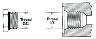
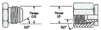
This commonly used connection incorporates two methods of sealing. The male NPTF (Dryseal) tapered thread will mate with the NPTF tapered female, which is usually a port and seal when the special threads are crushed together. Male NPTF (Short Dryseal) are identical to male NPTF threads except that the thread lengths have been shortened by one full thread from the small end of the taper. Additional sealing aids such as pipe dope and Teflon tape are often used with these threads. If the male has a 30° seat it will mate with the 30° cone seat in the NPSM straight thread swivel female, usually found on adapters, and is mechanically held together by the threads. NPTF and NPSM are not interchangeable with the British pipe threads.
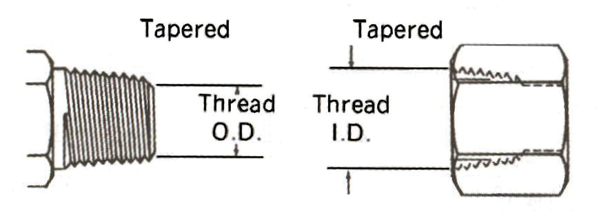
NPTF Tapered
NPSM Straight
| DashSize |
InchSize |
Threadper in |
Male Thread ODmm / in |
Female Thread IDmm / in |
| 2 | 1/8" | 27 | 10.3 / 0.41 | 9.4 / 0.37 |
| 4 | 1/4" | 18 | 13.7 / 0.54 | 12.4 / 0.49 |
| 6 | 3/8" | 18 | 17.3 / 0.68 | 15.7 / 0.62 |
| 8 | 1/2" | 14 | 21.6 / 0.85 | 19.3 / 0.76 |
| 12 | 3/4" | 14 | 26.9 / 1.06 | 24.9 / 0.98 |
| 16 | 1" | 11.5 | 33.8 / 1.33 | 31.5 / 1.24 |
| 20 | 1-1/4" | 11.5 | 42.2 / 1.67 | 40.1 / 1.58 |
| 24 | 1-1/2" | 11.5 | 48.5 / 1.91 | 46.2 / 1.82 |
| 32 | 2" | 11.5 | 60.4 / 2.38 | 57.9 / 2.28 |
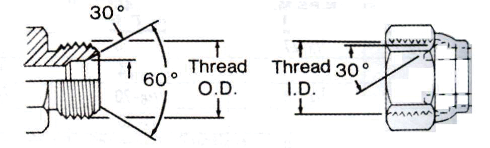
The British BSP connections include two types of threads, BSPP which are straight (or parallel) and BSPT which are tapered. The BSPT tapered male will mate with a BSPT tapered female (usually a port) and seals on the threads. The BSPP parallel male has a 30° chamfered seat which seals with a BSPP swivel female on its 30° cone seat. (Similar to the American NPSM-NPTF connection, however the BSPP swivel female end is commonly found on couplings.) The BSP threads are similar to, but not interchangeable with American NPTF pipe threads. The thread pitch is different in most sizes, and the thread angle is 55° instead of 60° angle found on NPTF and NPSM threads.
BSPP Parallel
BSPT Tapered
| DashSize |
InchSize |
Threadper in |
Male Thread ODmm / in |
Female Thread IDmm / in |
| 2 | 1/8" | 28 | 9.4 / 0.41 | 9.4 / 0.37 |
| 4 | 1/4" | 19 | 13.7 / 0.54 | 12.4 / 0.49 |
| 6 | 3/8" | 19 | 17.3 / 0.68 | 15.7 / 0.62 |
| 8 | 1/2" | 14 | 21.3 / 0.84 | 19.3 / 0.76 |
| 10 | 5/8" | 14 | 22.9 / 0.90 | 21.1 / 0.83 |
| 12 | 3/4" | 14 | 26.9 / 1.06 | 24.9 / 0.98 |
| 16 | 1" | 11 | 33.3 / 1.31 | 31.5 / 1.24 |
| 20 | 1-1/4" | 11 | 42.2 / 1.66 | 40.1 / 1.58 |
| 24 | 1-1/2" | 11 | 48.3 / 1.90 | 46.2 / 1.82 |
| 32 | 2" | 11 | 60.4 / 2.38 | 57.9 / 2.29 |
Commonly referred to as 37° JIC, this connection is widely used in hydraulic systems. When the straight threads are engaged, the 37° male seat seals on the 37° female flare seat. Most thread sizes are identical to the 45° SAE connection as noted (*) below. Care must be taken not to confuse these two connectors, which have different seat angles.
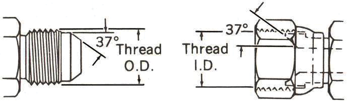
JIC Male
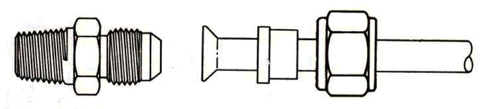
JIC Tube
| DashSize |
InchSize |
Threadper in |
Male Thread ODmm / in |
Female Thread IDmm / in |
| 2 | 1/8" | 24 | 7.9 / 0.31 | 6.9 / 0.27 |
| 3 | 3/16" | 24 | 9.6 / 0.38 | 8.6 / 0.34 |
| 4 | 1/4" | 20 | 11.2 / 0.44 | 9.9 / 0.39 |
| 5 | 5/16" | 20 | 12.7 / 0.50 | 11.4 / 0.45 |
| 6 | 3/8" | 18 | 14.2 / 0.56 | 12.9 / 0.51 |
| 8 | 1/2" | 16 | 19.0 / 0.75 | 17.0 / 0.67 |
| 10 | 5/8" | 14 | 22.3 / 0.88 | 20.3 / 0.80 |
| 12 | 3/4" | 12 | 26.9 / 1.06 | 24.9 / 0.98 |
| 14 | 7/8" | 12 | 30.2 / 1.19 | 27.9 / 1.10 |
| 16 | 1" | 12 | 33.3 / 1.31 | 31.0 / 1.22 |
| 20 | 1-1/4" | 12 | 41.4 / 1.63 | 39.1 / 1.54 |
| 24 | 1-1/2" | 12 | 47.7 / 1.88 | 45.5 / 1.79 |
| 32 | 2" | 12 | 63.5 / 2.50 | 61.2 / 2.41 |
This Japanese connector is similar to American 37° JIC flare except for the 30° seat angle. The straight (parallel) threads are the same as BSPP.
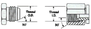
JIS 30° Flare
| DashSize |
InchSize |
Threadper in |
Male Thread ODmm / in |
Female Thread IDmm / in |
| 2 | 1/8" | 28 | 9.4 / 0.37 | 8.1 / 0.32 |
| 4 | 1/4" | 19 | 13.7 / 0.53 | 12.4 / 0.49 |
| 6 | 3/8" | 19 | 17.2 / 0.68 | 16.0 / 0.62 |
| 8 | 1/2" | 14 | 21.5 / 0.84 | 19.8 / 0.77 |
| 10 | 5/8" | 14 | 23.1 / 0.91 | 20.6 / 0.81 |
| 12 | 3/4" | 14 | 36.9 / 1.06 | 25.4 / 1.00 |
| 16 | 1" | 11 | 34.0 / 1.34 | 31.8 / 1.25 |
| 20 | 1-1/4" | 11 | 42.6 / 1.68 | 40.4 / 1.59 |
| 24 | 1-1/2" | 11 | 48.5 / 1.90 | 46.2 / 1.81 |
| 32 | 2" | 11 | 60.4 / 2.37 | 58.2 / 2.29 |
This straight thread connection uses the same threads as the JIC 37° shown above. However the 37° flare has been removed and an o-ring has been added. When mated with a female o-ring boss port the o-ring is trapped in a special tapered counter bore to affect the seal.
O-Ring Boss
| DashSize |
InchSize |
Threadper in |
Male Thread ODmm / in |
Female Thread IDmm / in |
| 2 | 1/8" | 24 | 7.9 / 0.31 | 6.9 / 0.27 |
| 3 | 3/16" | 24 | 9.6 / 0.38 | 8.6 / 0.34 |
| 4 | 1/4" | 20 | 11.2 / 0.44 | 9.9 / 0.39 |
| 5 | 5/16" | 20 | 12.7 / 0.50 | 11.4 / 0.45 |
| 6 | 3/8" | 18 | 14.2 / 0.56 | 12.9 / 0.51 |
| 8 | 1/2" | 16 | 19.0 / 0.75 | 17.0 / 0.67 |
| 10 | 5/8" | 14 | 22.3 / 0.88 | 20.3 / 0.80 |
| 12 | 3/4" | 12 | 26.9 / 1.06 | 24.9 / 0.98 |
| 16 | 1" | 12 | 33.3 / 1.31 | 31.0 / 1.22 |
| 20 | 1-1/4" | 12 | 41.4 / 1.63 | 39.1 / 1.54 |
| 24 | 1-1/2" | 12 | 47.7 / 1.88 | 45.5 / 1.79 |
| 32 | 2" | 12 | 63.5 / 2.50 | 61.2 / 2.41 |
This connection is designed for leak-free use to 6000 PSI. The O-ring in the face of the straight thread male end seals against the flat face female seat and is mechanically held in place by a swivel female nut.
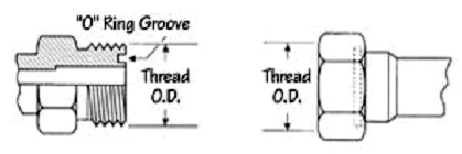
O-Ring Face Seal
| DashSize |
InchSize |
Threadper in |
Male Thread ODmm / in |
Female Thread IDmm / in |
| 2 | 1/8" | 24 | 7.9 / 0.31 | 6.9 / 0.27 |
| 3 | 3/16" | 24 | 9.6 / 0.38 | 8.6 / 0.34 |
| 4 | 1/4" | 20 | 11.2 / 0.44 | 9.9 / 0.39 |
| 5 | 5/16" | 20 | 12.7 / 0.50 | 11.4 / 0.45 |
| 6 | 3/8" | 18 | 14.2 / 0.56 | 12.9 / 0.51 |
| 8 | 1/2" | 16 | 19.0 / 0.75 | 17.0 / 0.67 |
| 10 | 5/8" | 14 | 22.3 / 0.88 | 20.3 / 0.80 |
| 12 | 3/4" | 12 | 26.9 / 1.06 | 24.9 / 0.98 |
| 16 | 1" | 12 | 33.3 / 1.31 | 31.0 / 1.22 |
| 20 | 1-1/4" | 12 | 41.4 / 1.63 | 39.1 / 1.54 |
| 24 | 1-1/2" | 12 | 47.7 / 1.88 | 45.5 / 1.79 |
| 32 | 2" | 12 | 63.5 / 2.50 | 61.2 / 2.41 |
The SAE 45° flare connectors seal in the same manner and are similar to the 37° connectors except for the flare angle. When the straight threads are engaged, the 45° male seat seals on the 45° female flare seat. 45° connectors are commonly found in automotive and refrigeration applications, on brass adapters, and are generally used at lower pressures than 37° JIC connectors. Check the threads and flares carefully to make positive identification.
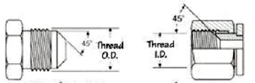
SAE 45° Flare
| DashSize |
InchSize |
Threadper in |
Male Thread ODmm / in |
Female Thread IDmm / in |
| 2 | 1/8" | 24 | 7.9 / 0.31 | 6.9 / 0.27 |
| 3 | 3/16" | 24 | 9.6 / 0.38 | 8.6 / 0.34 |
| 4 | 1/4" | 20 | 11.2 / 0.44 | 9.9 / 0.39 |
| 5 | 5/16" | 20 | 12.7 / 0.50 | 11.4 / 0.45 |
| 6 | 3/8" | 18 | 15.7 / 0.62 | 14.2 / 0.56 |
| 8 | 1/2" | 16 | 19.0 / 0.75 | 17.0 / 0.67 |
| 10 | 5/8" | 14 | 22.3 / 0.88 | 20.3 / 0.80 |
| 12 | 3/4" | 12 | 26.9 / 1.06 | 24.9 / 1.09 |
| 14 | 7/8" | 12 | 31.7 / 1.25 | 29.5 / 1.16 |
| 16 | 1" | 12 | 35.0 / 1.38 | 32.5 / 1.28 |
This connector system consist of one male and three styles of female, all of which have straight metric threads. Sealing takes place between the 24° seat in the male end and the respective sealing area in the female ends. DIN 2353 includes both a light and heavy duty series which can be identified by measuring the tube OD.
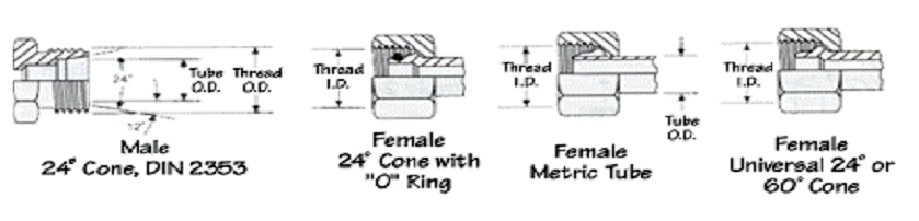
DIN 2353
| Threadmm |
Male Thread ODmm / in |
Female Thread IDmm / in |
Tube ODLight / Heavy mm |
| M12x1.5 | 12 / 0.47 | 10.5 / 0.41 | 6 / - |
| M14x1.5 | 14 / 0.55 | 11.5 / 0.49 | 8 / 6 |
| M16x1.5 | 16 / 0.63 | 14.5 / 0.57 | 10 / 8 |
| M18x1.5 | 18 / 0.71 | 16.5 / 0.65 | 12 / 10 |
| M20x1.5 | 20 / 0.78 | 18.5 / 0.73 | - / 12 |
| M22x1.5 | 22 / 0.87 | 20.5 / 0.81 | 15 / 14 |
| M24x1.5 | 24 / 0.94 | 22.5 / 0.89 | - / 16 |
| M26x1.5 | 26 / 1.02 | 24.5 / 0.96 | 18 / - |
| M30x2 | 30 / 1.18 | 28 / 1.11 | 22 / 20 |
| M36x2 | 36 / 1.41 | 34 / 1.34 | 28 / 25 |
| M42x2 | 42 / 1.65 | 40 / 1.57 | - / 30 |
| M45x2 | 45 / 1.77 | 43 / 1.70 | 35 / - |
| M52x2 | 52 / 2.04 | 50 / 1.97 | 42 / 38 |
The imperial size flareless fitting utilizes a metal to metal seal between the 24° seat on the male threaded fitting and either a compression sleeve on a piece of tube, stand-pipe or 24° ball nose machined fitting. To achieve a leak free connection all sealing surfaces must be smooth and free of any damage or contamination.
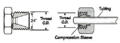
Flareless Tube
| DashSize |
InchSize |
Threadper in |
Male Thread ODmm / in |
Female Thread IDmm / in |
| 2 | 1/8" | 24 | 7.9 / 0.31 | 6.9 / 0.27 |
| 3 | 3/16" | 24 | 9.6 / 0.38 | 8.4 / 0.33 |
| 4 | 1/4" | 20 | 11.2 / 0.44 | 9.9 / 0.39 |
| 5 | 5/16" | 20 | 12.7 / 0.50 | 11.4 / 0.45 |
| 6 | 3/8" | 18 | 14.2 / 0.56 | 12.7 / 0.50 |
| 8 | 1/2" | 16 | 19.0 / 0.75 | 17.5 / 0.69 |
| 10 | 5/8" | 14 | 22.3 / 0.88 | 20.7 / 0.81 |
| 12 | 3/4" | 12 | 26.9 / 1.06 | 24.6 / 0.97 |
| 14 | 7/8" | 12 | 30.2 / 1.19 | 28.2 / 1.11 |
| 16 | 1" | 12 | 33.3 / 1.31 | 31.2 / 1.23 |
| 20 | 1-1/4" | 12 | 41.6 / 1.63 | 39.3 / 1.55 |
| 24 | 1-1/2" | 12 | 47.6 / 1.88 | 45.6 / 1.80 |
Used extensively on Komatsu equipment, this 30° flare connector has parallel metric threads and is sometimes confused with JIS 30° flare which has parallel threads.
Komatsu 30°
| DashSize |
MetricSize |
Thread |
Male Thread ODmm / in |
Female Thread IDmm / in |
| 6 | 9 | M18x1.5 | 18 / 0.71 | 16.5 / 0.65 |
| 8 | 12 | M22x1.5 | 22 / 0.87 | 20.5 / 0.82 |
| 10 | 16 | M24x1.5 | 24 / 0.94 | 22.5 / 0.88 |
| 12 | 19 | M30x1.5 | 30 / 1.18 | 28.5 / 1.12 |
| 16 | 25 | M33x1.5 | 33 / 1.30 | 31.5 / 1.24 |
| 20 | 32 | M36x1.5 | 36 / 1.42 | 34.5 / 1.36 |
| 24 | 38 | M42x1.5 | 42 / 1.65 | 40.5 / 1.59 |
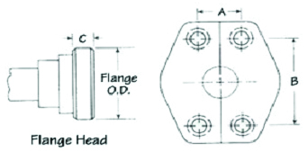
4 Bolt Flange
| DashSize |
InchSize |
Code 61PSI / Flange OD |
Code 62PSI / Flange OD |
ThicknessC62 / Cat |
| 8 | 1/2" | 5000 / 1.188" | 6000 / 1.250" | 0.305" / - |
| 10 | 5/8" | - / 1.345" | - / - | - / - |
| 12 | 3/4" | 5000 / 1.500" | 6000 / 1.625" | 0.345" / 0.560" |
| 16 | 1" | 5000 / 1.750" | 6000 / 1.875" | 0.375" / 0.560" |
| 20 | 1-1/4" | 4000 / 2.000" | 6000 / 2.125" | 0.405" / 0.560" |
| 24 | 1-1/2" | 3000 / 2.375" | 6000 / 2.500" | 0.494" / 0.560" |
| 32 | 2" | 3000 / 2.813" | 6000 / 3.125" | 0.495" / 0.560" |
| 40 | 2-1/2" | 2500 / 3.312" | - / - | - / - |
| 48 | 3" | 2000 / 4.000" | - / - | - / - |
| DashSize |
ORBID x W |
OFSID x W |
C61 & C62ID x W |
BSPP BondedOD x W |
| -2 | 0.24x0.06" | - | - | 0.63x0.08" |
| -3 | 0.30x0.06" | - | - | - |
| -4 | 0.35x0.07" | 0.30x0.07" | - | 0.81x0.08" |
| -5 | 0.41x0.07" | - | - | - |
| -6 | 0.47x0.08" | 0.36x0.07" | - | 0.94x0.08" |
| -8 | 0.64x0.08" | 0.49x0.07" | 0.73x0.14" | 1.13x0.09" |
| -10 | 0.76x0.10" | 0.61x0.07" | - | 1.25x0.09" |
| -12 | 0.92x0.12" | 0.74x0.07" | 0.98x0.14" | 1.37x0.09" |
| -14 | 1.05x0.12" | - | - | - |
| -16 | 1.17x0.12" | 0.93x0.07" | 1.30x0.14" | 1.69x0.09" |
| -20 | 1.48x0.12" | 1.18x0.07" | 1.48x0.14" | 2.06x0.13" |
| -24 | 1.72x0.12" | 1.49x0.07" | 1.86x0.14" | 2.31x0.13" |
| -32 | 2.34x0.12" | - | 2.23x0.14" | - |